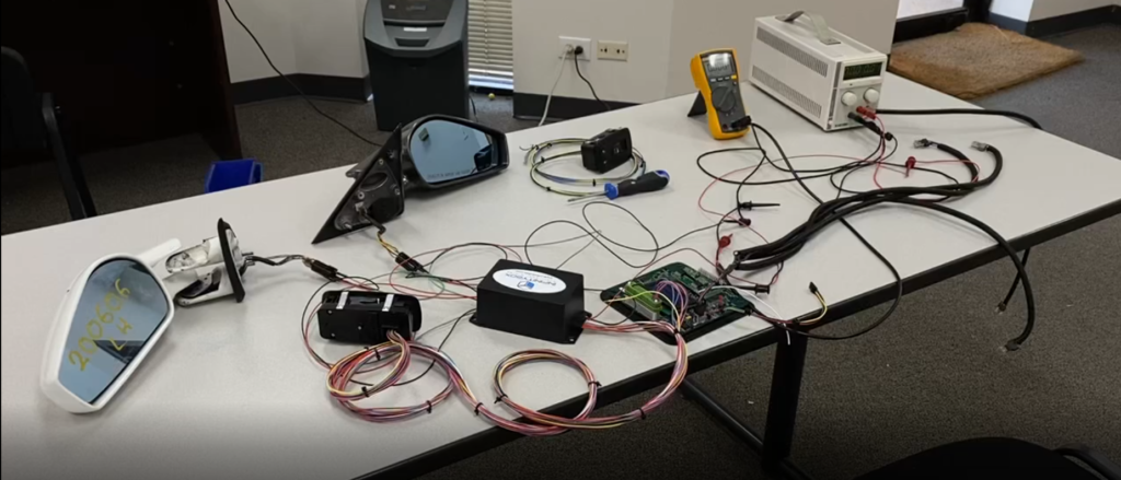
In this project, I was tasked with designing a system that would control a pair of side mirrors from a Ferrari F430, using two side mirror controllers taken from an early dodge charger. I had to design multiple PCB’s or printed circuit boards, to interface with the side mirror controllers, and to control said side mirrors while sending additional switch and button data to the Infinitybox 20 Circuit Kit.
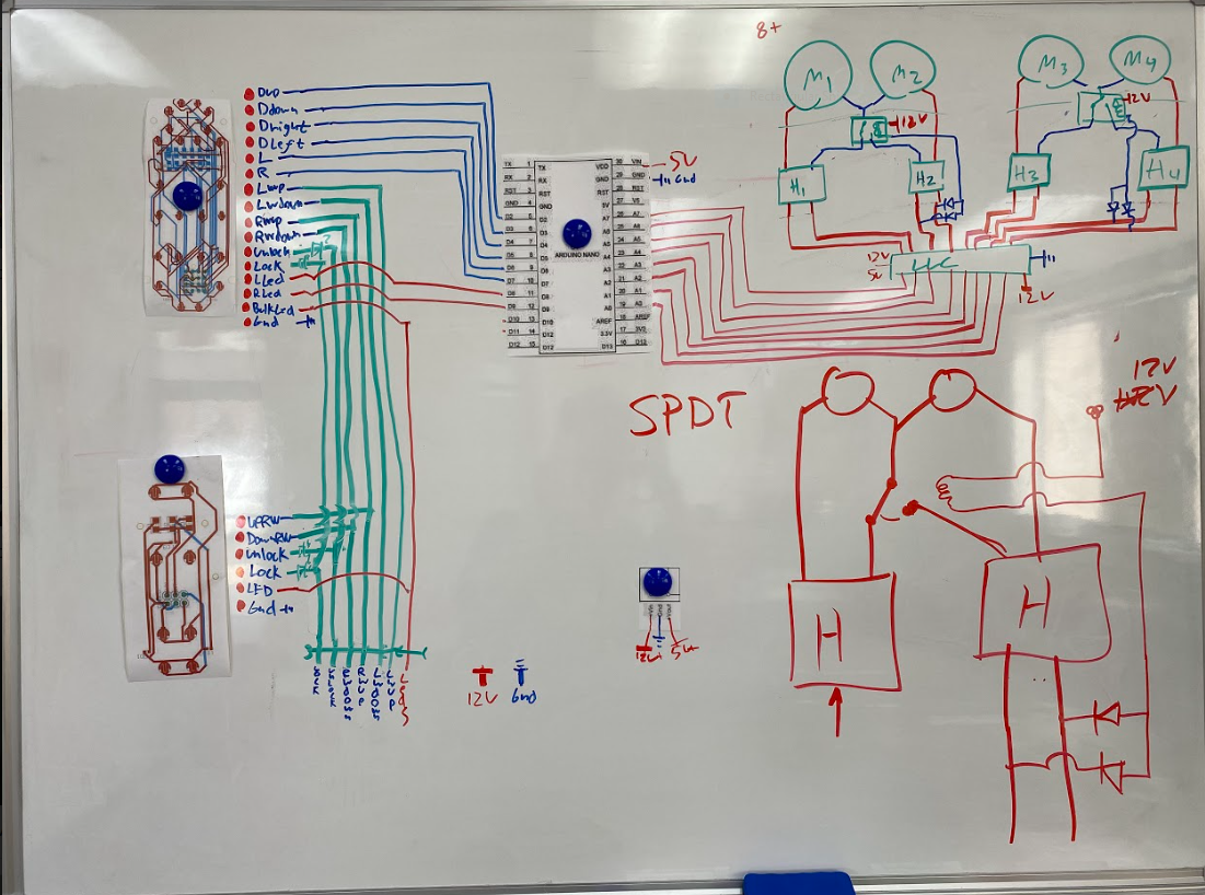
The first thing I did was plan out how the total system would work.
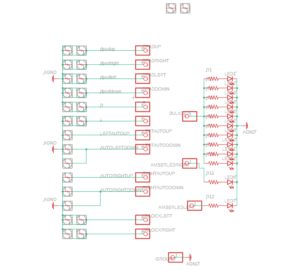
For details I will explain later we need to design 3 boards.
One to interface with the controller board in the driver-side door, another for the passenger-side door, and one that actually controls the lighting and motors that control the side mirrors. The system also gets connected to the Infinitybox Mastercell Inputs.

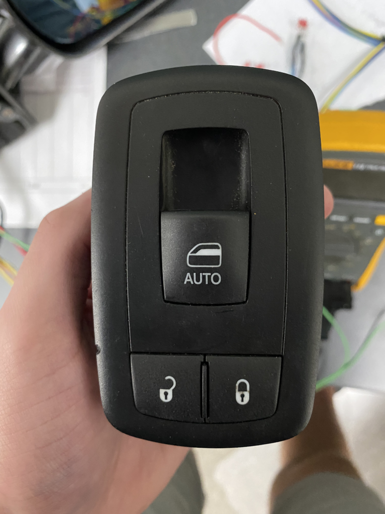
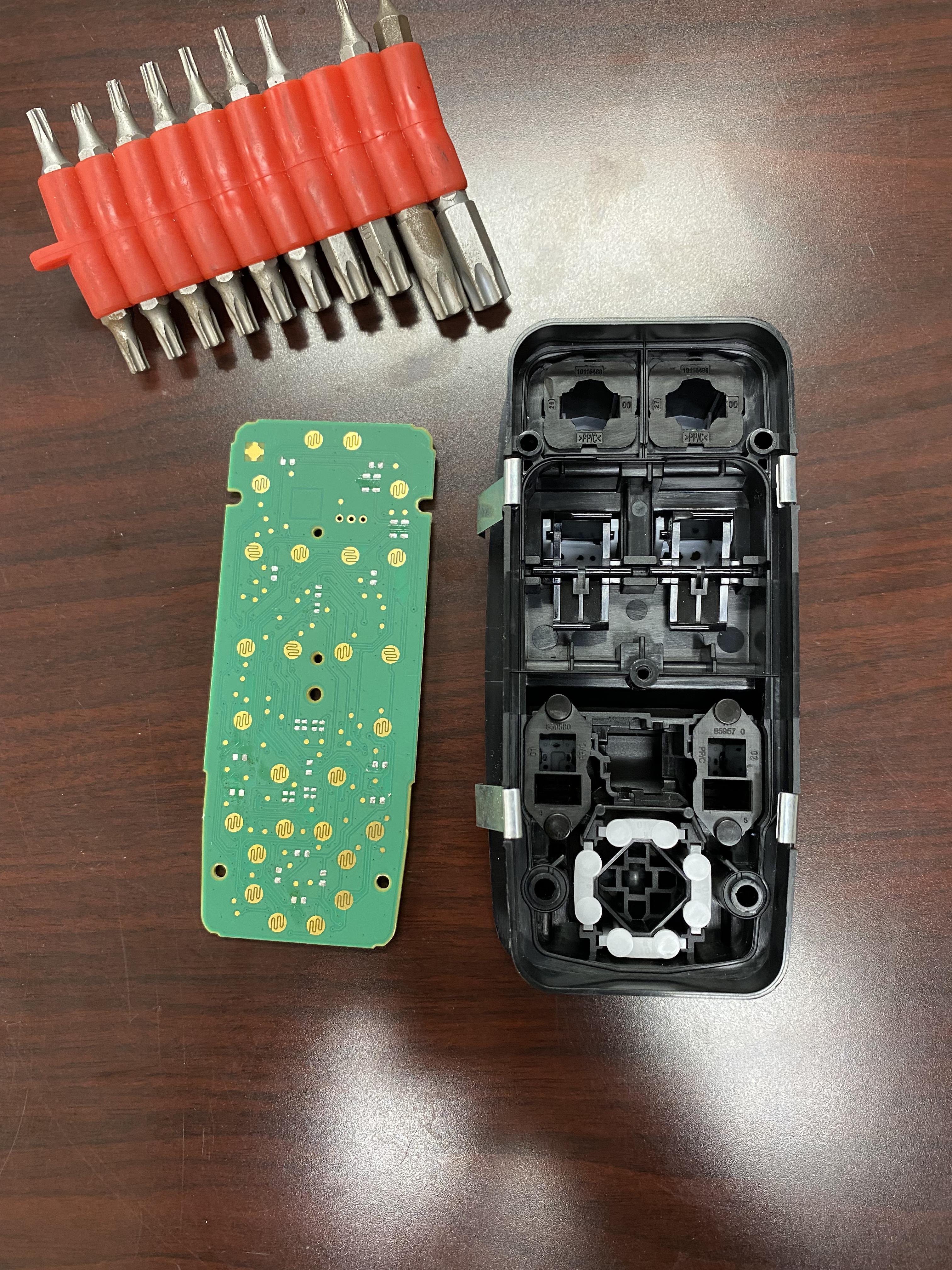
The first thing I did was see how the side mirror controllers functioned.
Since the board had 3 breakout points and contained the appropriate ICs. I concluded that the board used LIN to communicate. LIN is a single-wire protocol, that requires a LIN master node to send an initiation frame to even get any data and there are much simpler ways to interface with the buttons than setting up a whole LIN atmosphere and decoding the actual LIN communications.
Looking at the injection molded casing in more detail. There’s some cool stuff going on but it boils down to small conductive pads that either are or aren’t in contact with the PCB below.
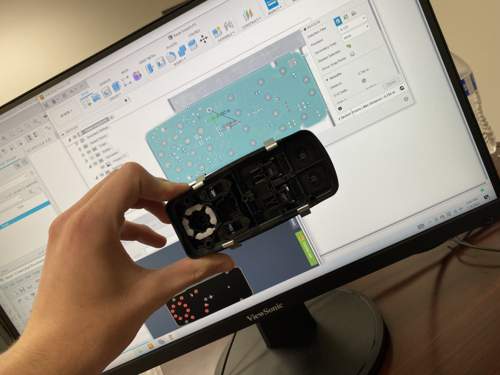
I used a photocopier to make sure that the dimensions were accurate, and used fusion 360 to design an object that had holes where all the pads were. Then I used eagle to design a 2-layer PCB to not only have the contact pads but also have light LEDs and indicator LEDs for the switches on the top of the board.
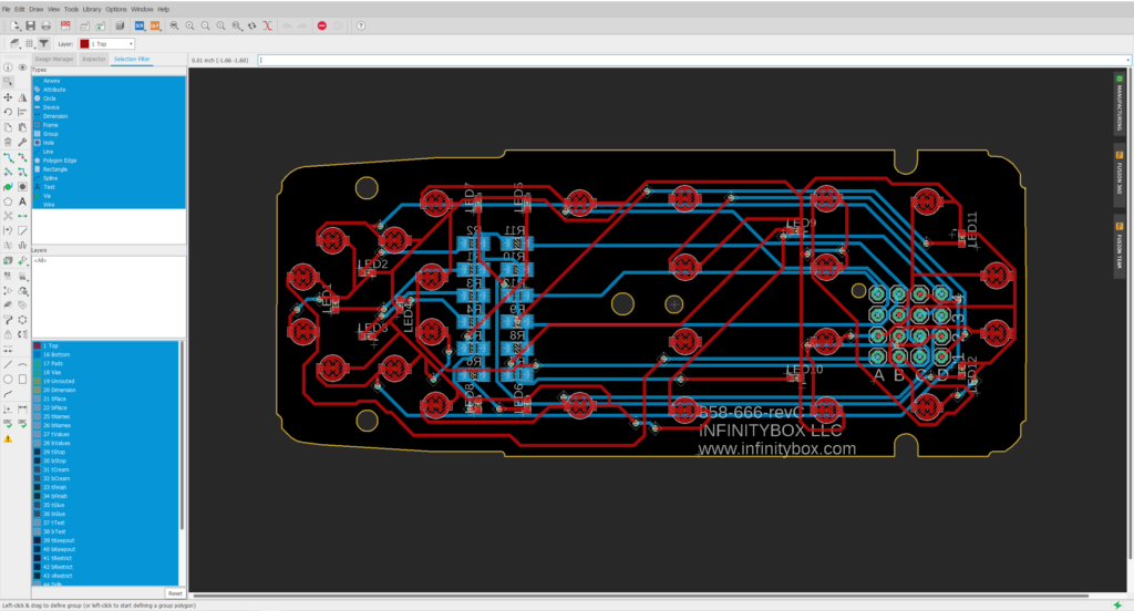
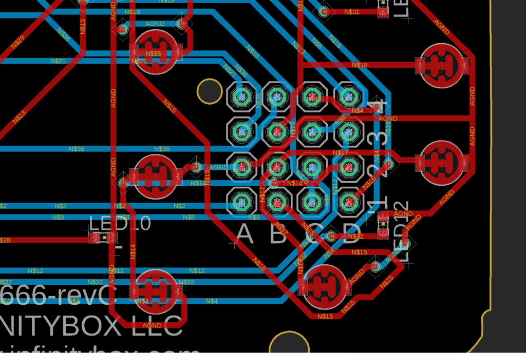
Additionally, I also made a matrix grid for the direct outputs of the pads that will be connected through a wire harness to the inputs on the Infinitybox Mastercell.